On some Audi vehicles very common failures may occur when installing the Audi Navigation Plus RNS-E or BNS 5.0 systems:
- 00858 - Connection; Radio ZF Output to Antenna Amplifier
- 007 - Short to Ground
We explain why this happens:
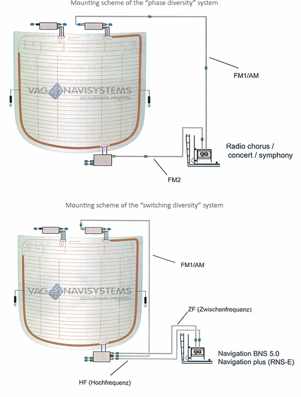
- In Audi vehicles from week 22/2004 the radio models "Chorus , Concert and Symphony" are equipped with a second antenna connection "phase diversity", in this way the radio selects the corresponding antenna in case of loss of signal.
- From week 45/2006 the generation of Radios II+ (2din) is introduced. They have two internal tuners for signal reception with “phase diversity” and works the same way as the previous generation.
- The RNS-E and BNS 5.0 navigation systems uses an external antenna selection module with the "switching diversity" system. The "switching diversity" system it's along with the "phase diversity" system the second method to reduce disturbances in signal reception.
- Thereby to operate with this two systems: "switching diversity" and "phase diversity" it's required at least two antennas with amplifier and a radio with two internal tuners. So if the received signal suffers some disturbance, both rear signals to the radio tuners will be digitized and separated, so that interference signals are suppressed for the most part.
- If the signal is not disturbed, the radio continuously compares which of the two antennas receives the strongest signal. The second tuner scans in the background the frequency band in order to find better signal reception frequencies for the current station. If there is a better signal this second tuner will starts to receive the antenna signal and the other tuner pass to background.
- In the case of the RNS-E or the BNS 5.0 this whole work is performed by an external module.
Operation scheme of the systems:
Once the operation of the systems it's understood, we will solve this faults:
The following examples are for the Audi A3 (8P). In other vehicle models teh position may change, the modules to use, the products references, and/or the installation wires.
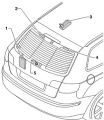
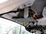
Location of the antenna amplifiers:
- Main antenna module (selection)
- Left antenna amplifier
- Roof antenna (GSM/GPS/RC)
- Right antenna amplifier
The modules to replace in this case will be the num. 1 (Main antenna module) and the num. 2 (Left antenna amplifier).
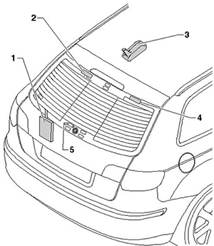
Image 1
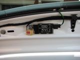
Steps for replacing the Main antenna module and the Left antenna amplifier:
- The first step is to remove the plastics and upholstery of the tailgate.
- Once removed, will identify the Left antenna amplifier (num. 2)
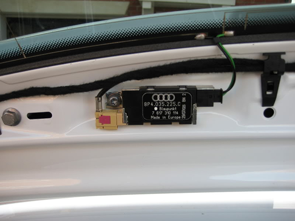
Image 2
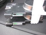
- This amplifier must be replaced, and the antenna cable of the brown Fakra connector redirected to the main antenna module (selection) (num. 1)
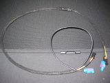
- For this we will use the wiring of the following image:
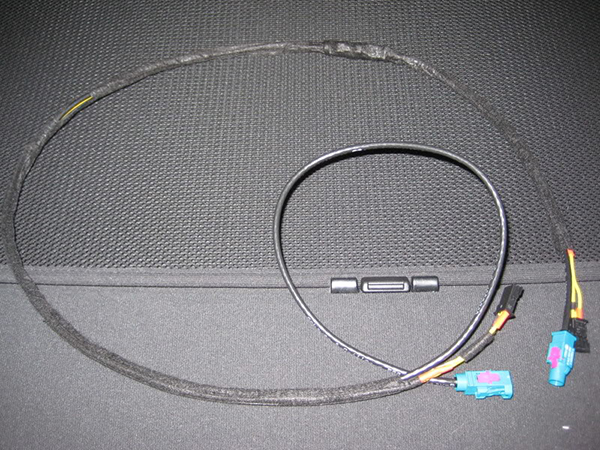
Image 3
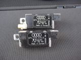
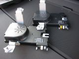
- Then, it will be necessary to replace the Left antenna amplifier (image 2) by the corresponding amplifier for the vehicle, without the antenna Fakra connector, amplifier bottom of the following image:
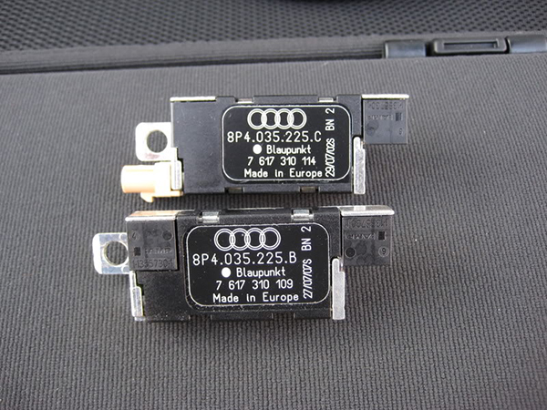
Image 4
- Using the prepared wiring as shown in the image 3, it will be necessary to connect the various connectors of the amplifier without Fakra, as shown in the following image:
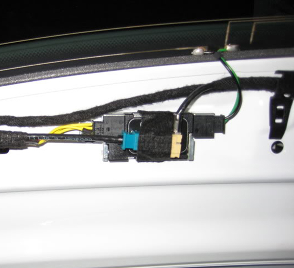
Image 5
- Then we will replace the main antenna module (selection)
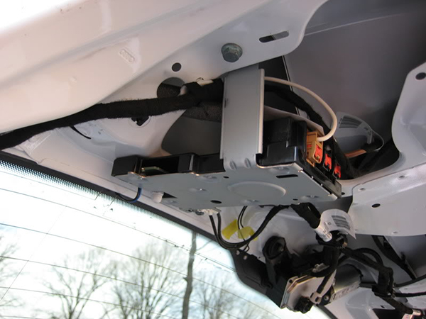
Image 6
- For this it will be necessary to disconnect all the connectors of the main antenna module, and its fixing screws.
- In the following image shown that the new main antenna module at the top of the image, incorporates a new Fakra antenna connector, brown/mustard color.
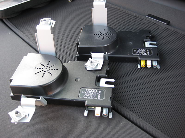
Image 7
- This new module, also incorporates the connector for signals from the left amplifier connected to the windscreen.

Image 8
- The last step is to place the new main antenna module (selection) in its proper location, connect the remainig wires of the prepared wiring (image 3) to the new module, and the connectors previously disconnected of the previous main antenna module.
- Test the system, clear faults (if any) and close the upholstery/plastics of the tailgate.
- In this way and following all these steps we have solved the problem of radio reception.
You can adquire all the components of this retrofit kit by clicking the following link:


 DEALS
DEALS INFOCENTER
 CONTACT